


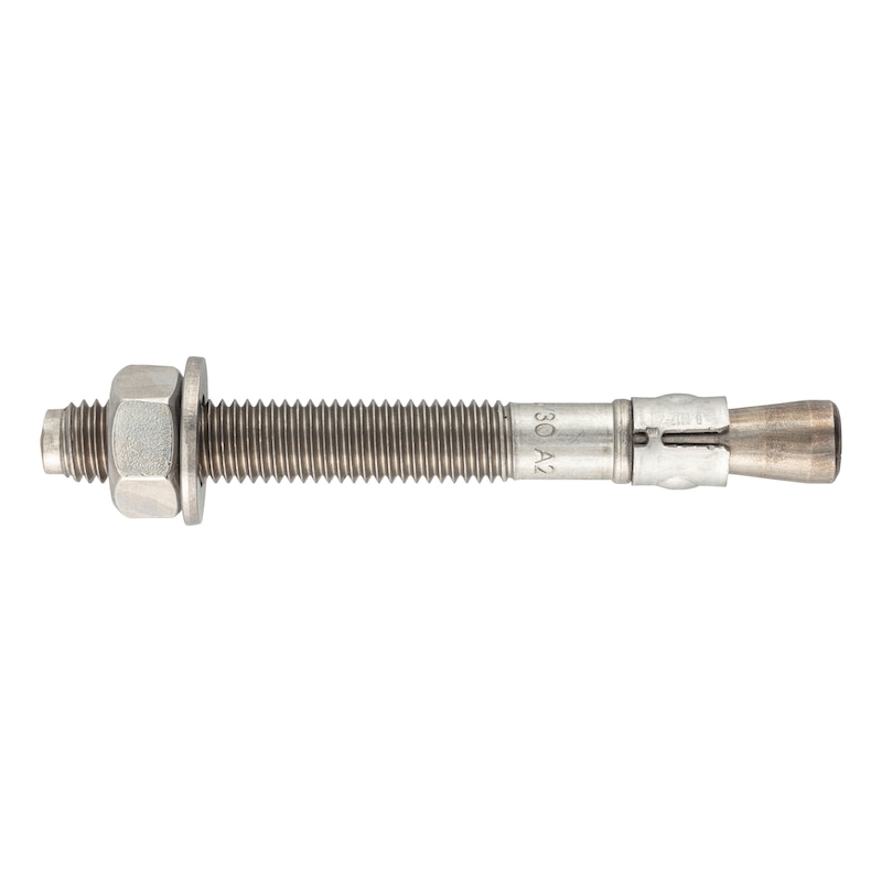


Fixanchor W-FA/A2
Fixanchor W-FA stainless steel A2
ANC-(W-FA/A2)-A2-13-45-51-M10X120
Art.-no. 5932410120
EAN 4065746037044


Register now and access more than 125,000 products
- Economical fastening solution for standard applications in uncracked concrete
- Very flexible application thanks to three effective anchorage depths
- Extra-small effective anchorage depths minimise drilling and installation effort
- Small spacings and edge distances
Before using anchors for uncracked concrete in areas subject to building regulations or safety regulations, proof must be provided in accordance with DIN EN 1992-4 that the concrete will be in an uncracked state for the service life of the fastening.
European Technical Assessment ETA-02/0001 for individual fixing point, option 7, uncracked concrete:
- Static or quasi-static action (M6-M20)
Datasheets(X)

Individual fixing point with approval/assessment
In uncracked normal weight concrete C20/25 to C50/60
Suitable for anchoring medium-heavy to heavy loads in uncracked concrete:
- Fastening metal constructions, metal profiles, base plates, wooden structures, beams, fence systems, startup protection, etc. in pre-positioned installation, push-through installation and stand-off installation.
The W-FA/A2 (A2 stainless steel) is suitable for use in dry indoor environments and for outdoor applications in corrosion resistance class CRC II in accordance with DIN EN 1993-1-4:2015.
For use in concrete < C20/25 and pressure-resistant natural stone (without approval/assessment)
Metric anchor diameter | M10 |
Anchor length (l) | 120 mm |
Material | Stainless steel A2 |
Attachment height (t fix 1) | 51 mm |
Attachment height (t fix 2) | 45 mm |
Attachment height (t fix 3) | 13 mm |
Drill hole depth (h 1.1) | 65 mm |
Drill hole depth (h 1.2) | 70 mm |
Drill hole depth (h 1.3) | 102 mm |
Effective anchoring depth (h ef 1) | 42 mm |
Effective anchoring depth (h ef 2) | 48 mm |
Effective anchoring depth (h ef 3) | 80 mm |
Embedding depth (h nom1) | 56 mm |
Embedding depth (h nom2) | 94 mm |
Embedding depth (h nom3) | 94 mm |
Washer diameter | 20 mm |
Width across flats | 17 mm |
Nominal drill-bit diameter (d 0) | 10 mm |
Torque during anchoring (T inst) | 25 Nm |
Through-hole in the component to be connected (d f) | 12 mm |
Thread length (L th) | 75 mm |
Type of assembly | Pre-setting installation, Through-setting installation, Stand-off installation |
Approval | ETA-02/0001 |
| Performance data in uncracked concrete - individual fixing point in accordance with ETA-02/0001 without the influence of spacings and edge distances | |||||||||||||||||||
| Anchor size [mm] | M6 | M8 | M10 | M12 | M16 | ||||||||||||||
| Effective anchorage depth [mm] | hef,1 | hef,2 | hef,3 | 303) | 40 | 60 | 353) | 44 | 70 | 42 | 48 | 80 | 50 | 65 | 100 | 64 | 82 | 120 | |
| Embedment depth [mm] | hnom,1 | hnom,2 | hnom,3 | 393) | 49 | 69 | 473) | 56 | 82 | 56 | 62 | 94 | 67 | 82 | 117 | 84 | 102 | 140 | |
| Adm. tensile load1) | Uncracked concrete C20/252), s ≥ 3 hef c ≥ 1.5 hef | Nadm [kN] = C20/252) | 3,1 | 3,8 | 3,8 | 4,3 | 6,8 | 7,1 | 5,7 | 7,8 | 7,8 | 8,3 | 11,9 | 11,9 | 12,0 | 16,8 | 20,0 | ||
| Adm. shear load1) | Uncracked concrete C20/252), c ≥ 10 hef | Vadm [kN] = C20/252) | 4,0 | 6,9 | 10,9 | 15,4 | 28,6 | ||||||||||||
| Admissible bending moment | Madm [Nm] | 5,7 | 13,7 | 28,0 | 48,6 | 113,7 | |||||||||||||
| For admissible load when exposed to fire (R30, R60, R90, R120), please refer to European Technical Assessment ETA-02/0001 | |||||||||||||||||||
| 1) The partial safety factors of the resistances γM regulated in the approval/assessment and a partial safety factor of the actions of γF = 1.4 have been taken into account. For a combination of tensile and shear loads, for the influence of the edge distance and anchor groups, please see the appropriate guidelines e.g. DIN EN 1992-4. 2) The concrete has normal reinforcement. Higher values are possible for higher concrete compressive strengths. 3) Only for statically indeterminate non-load-bearing systems (anchors in a redundant non-structural system) in accordance with EN 1992-4 and only in dry indoor conditions | |||||||||||||||||||
| Installation parameters | |||||||
| Anchor size | M6 | M8 | M10 | M12 | M16 | ||
| Nominal drill diameter | d0 = | [mm] | 6 | 8 | 10 | 12 | 16 |
| Diameter of cutting edges | dcut ≤ | [mm] | 6,4 | 8,45 | 10,45 | 12,5 | 16,5 |
| Torque while installing anchor | Tinst = | [Nm] | 6 | 15 | 25 | 50 | 100 |
| Through hole in the attachment | df ≤ | [mm] | 7 | 9 | 12 | 14 | 18 |
| Width across flats | AF | [mm] | 10 | 13 | 17 | 19 | 24 |
| Height hexagon nut | tnut | [mm] | 5 | 6,5 | 8 | 10 | 13 |
| Height x dia. washer | tw x dw | [mm] | 1.6x12 | 1.6x16 | 2x20 | 2.5x24 | 3x30 |
| Effective anchorage depth hef,1 | |||||||
| Effective anchorage depth | hef,1 ≥ | [mm] | 30 | 35 | 42 | 50 | 64 |
| Drill hole depth | h1.1 ≥ | [mm] | 45 | 55 | 65 | 75 | 95 |
| Embedment depth | hnom,1 ≥ | [mm] | 39 | 47 | 56 | 67 | 84 |
| Minimum member thickness | hmin | [mm] | 80 | 80 | 100 | 100 | 130 |
| Characteristic spacing | scr,N | [mm] | 90 | 105 | 126 | 150 | 192 |
| Characteristic edge distance | ccr,N | [mm] | 45 | 52,5 | 63 | 75 | 96 |
| Minimum spacing | smin | [mm] | 35 | 60 | 55 | 100 | 110 |
| Minimum edge distance | cmin | [mm] | 40 | 60 | 65 | 100 | 110 |
| Effective anchorage depth hef,2 | |||||||
| Effective anchorage depth | hef,2 ≥ | [mm] | 40 | 44 | 48 | 65 | 80 |
| Drill hole depth | h1.2 ≥ | [mm] | 55 | 65 | 70 | 90 | 110 |
| Embedment depth | hnom,2 ≥ | [mm] | 49 | 56 | 62 | 82 | 102 |
| Minimum member thickness | hmin | [mm] | 100 | 100 | 100 | 130 | 160 |
| Characteristic spacing | scr,N | [mm] | 120 | 132 | 144 | 195 | 240 |
| Characteristic edge distance | ccr,N | [mm] | 60 | 66 | 72 | 97,5 | 120 |
| Minimum spacing | smin | [mm] | 35 | 35 | 45 | 60 | 80 |
| for c ≥ | [mm] | 40 | 65 | 70 | 100 | 120 | |
| Minimum edge distance | cmin | [mm] | 35 | 45 | 55 | 70 | 80 |
| for s ≥ | [mm] | 40 | 65 | 70 | 100 | 120 | |
| Effective anchorage depth hef,3 | |||||||
| Effective anchorage depth | hef,3 ≥ | [mm] | 60 | 70 | 80 | 100 | 120 |
| Drill hole depth | h1.3 ≥ | [mm] | 75 | 91 | 102 | 125 | 148 |
| Embedment depth | hnom,3 ≥ | [mm] | 69 | 82 | 94 | 117 | 140 |
| Minimum member thickness | hmin | [mm] | 120 | 126 | 132 | 165 | 208 |
| Characteristic spacing | scr,N | [mm] | 180 | 210 | 240 | 300 | 360 |
| Characteristic edge distance | ccr,N | [mm] | 90 | 105 | 120 | 150 | 180 |
| Minimum spacing | smin | [mm] | 35 | 40 | 55 | 75 | 90 |
| for c ≥ | [mm] | 40 | 65 | 70 | 100 | 120 | |
| Minimum edge distance | cmin | [mm] | 40 | 45 | 65 | 90 | 105 |
| for s ≥ | [mm] | 60 | 110 | 80 | 100 | 140 | |
Select RAL-colour code
!! NOTE: On-screen visualisation of the colour differs from real colour shade!!
Last viewed

Chemical injection mortar Concrete Multi WIT-UH 300

Mixer nozzle WIT-UH For concrete Multi WIT-UH 300 injection system

Threaded rod DIN 976-1 (shape A) with standard metric ISO thread, zinc-plated steel 8.8, blue passivated (A2K)

Micro-fibre cloth Universal

Corrosion protection spray

Hexagon Socket Head Cap Screw ISO 4762/DIN 912, steel 10.9, zinc-plated, blue passivated (A2K)

Suction lifter with two rigid heads

Round/small adapter for dent lifter and pin puller

Countersunk screw with hexagon socket, galvanised ISO 10642, steel 10.9, zinc-plated, blue passivated (A2K)

Lacquer coating system