


All-rounder injectable mortar WIT-VM 250
All-rounder chemical injection mortar WIT-VM 250
ANC-MORT-(WIT-VM250)-330ML
Art.-no. 0903450202
EAN 4053479305493


Register now and access more than 125,000 products
- Two-component resin mortar, styrene-free vinyl ester
- Individual fixing point for cracked and uncracked concrete, seismic performance category C1
W-VI-A anchor rod, W-VD-A anchor rod, standard threaded rod with acceptance test certificate 3.1
- Individual fixing point for masonry (system with WIT-SH perforated sleeve):
WIT-SH perforated sleeve, WIT-AS anchor rod, WIT-IG internally threaded sleeve
- Individual fixing point for masonry (system with SH perforated sleeve):
SH perforated sleeve, W-VI-A anchor rod, W-VI-IG internal thread anchor, standard threaded rod with acceptance test certificate 3.1
- Post-installed rebar connection
- European Technical Assessment ETA-12/0164: Individual fixing point + cracked and uncracked concrete (W-VD-A anchor rod, standard threaded rod with 3.1 acceptance test certificate), seismic performance category C1
- European Technical Assessment ETA-13/1040: Individual fixing point + masonry consisting of solid and perforated block, autoclaved aerated concrete (WIT-SH perforated sleeve, WIT-AS anchor rod, WIT-IG internally threaded sleeve, autoclaved aerated concrete only with WIT-SH 18x95 perforated sleeve)
- European Technical Assessment ETA-16/0757 and ETA-20/0854: Individual fixing point + masonry consisting of solid and perforated block, autoclaved aerated concrete (SH perforated sleeve, W-VI-A anchor rod, W-VI-IG internal thread anchor, threaded rod with acceptance test certificate 3.1, autoclaved aerated concrete only without perforated sleeve)
- European Technical Assessment ETA-12/0166: Post-installed rebar connection, 330 ml, 420 ml and 825 ml cartridges only
- EPD: Environmental product declaration in accordance with ISO 14025 and EN 15804+A2, EPD-AWU-20230406-CBA3
We recommend the Würth Technical Software for planning and dimensioning your assembly.
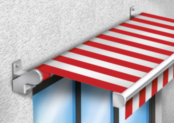 Awning
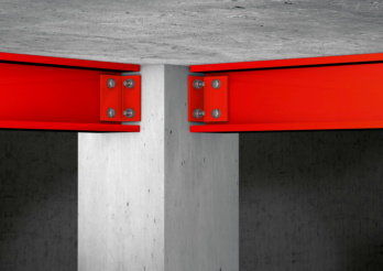 Steel supports
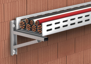 Brackets
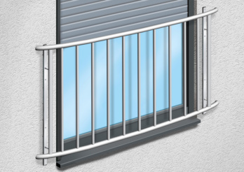 French balconies
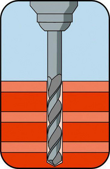
Drill holes with a rotary drill (without impact mechanism)
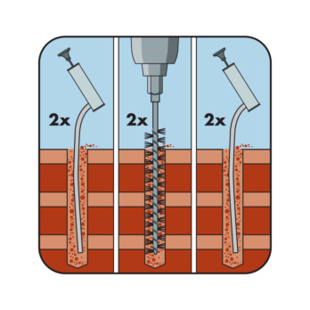
Clean the drill hole:
2x blow out/2x mechanical brush out/2x blow out
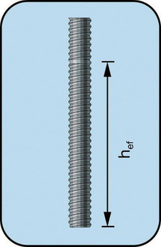
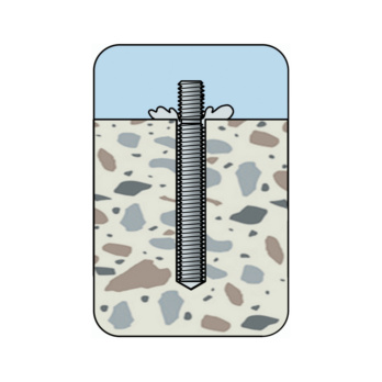
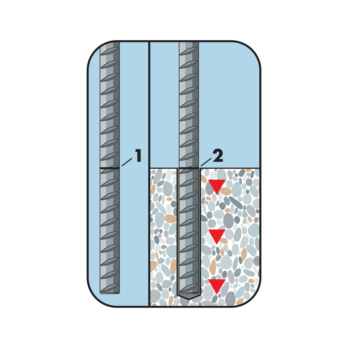
Cut anchor rod to length and mark the desired insertion depths

Insert perforated sleeve
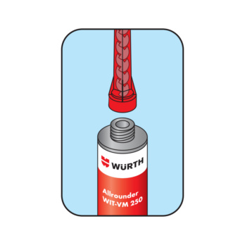
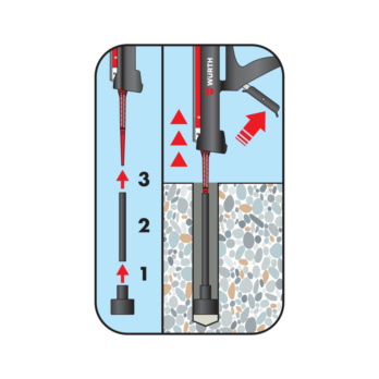
Screw mixer onto cartridge
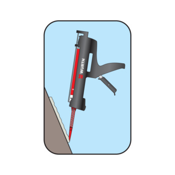
Discard the first section of mortar (until the mortar is uniformly coloured - approx. 10 cm)
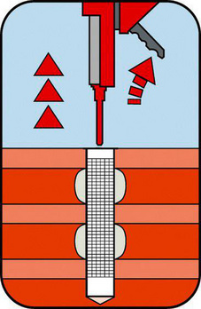
Completely fill with composite mortar from end of perforated sleeve
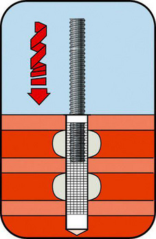
Press in anchor rod up to the bottom of the sleeve while turning slightly
Load can be applied to the reinforcement bar after observing the curing time
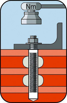
Mount component; do not exceed maximum torque
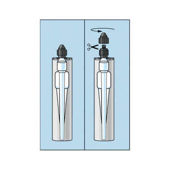
Cut tubular film clip before use!
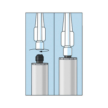
Screw mixer onto cartridge
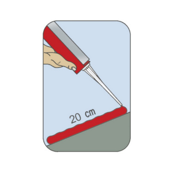
Before use, dispense a bead of approx. 20 cm
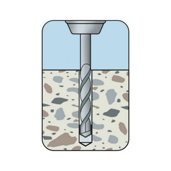
Create the drill hole
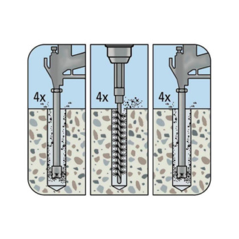
Clean the drill hole:
Blow out 4x with compressed air/brush out 4x mechanically/blow out 4x with compressed air
Cut anchor rod to length and mark the desired insertion depths
Screw mixer onto cartridge
Discard the first section of mortar (until the mortar is uniformly coloured - approx. 10 cm)
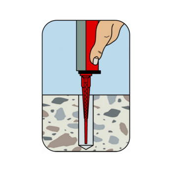
Fill composite mortar from bottom of drill hole
Press in anchoring element up to drill hole base while turning slightly
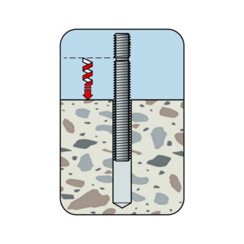
Visual check of mortar volume, embedment depth mark
Load can be applied to the reinforcement bar after observing the curing time
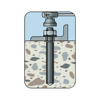
Mount the component. Do not exceed the maximum torque
Cut tubular film clip before use!
Screw mixer onto cartridge
Before use, dispense a bead of approx. 20 cm
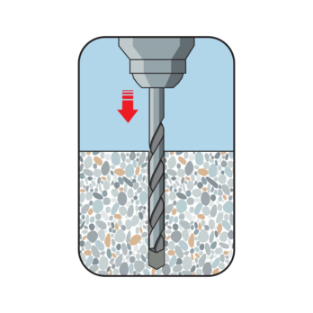
Drill the hole
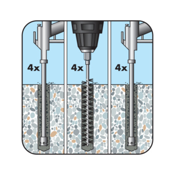
Clean the drill hole:
Blow out 4x with oil-free compressed air (min. 6 bar)
Brush out 4x mechanically
Blow out 4x with oil-free compressed air (min. 6 bar) (d. <20 mm and d. < 10xds)
Blow out 4x with hand pump, brush out 4x mechanically, blow out 4x with hand pump
Place the embedment depth mark on the rod and check the drilling hole depth
Screw mixer onto cartridge
Discard the first section of mortar (until the mortar is uniformly coloured - approx. 10 cm)
Mount injection equipment, fill composite mortar from bottom of drill hole
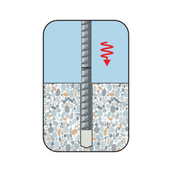
Insert the reinforcement bar until it reaches the mark, turning slightly
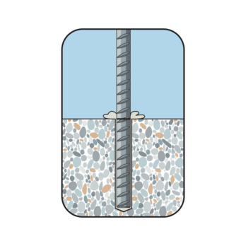
Visual check of the mortar volume, observe maximum processing time
Load can be applied to the reinforcement bar after observing the curing time
| Minimum curing times in concrete | |||
| Temperature of base material | Processing time | Minimum curing time in dry concrete | Minimum curing time in wet concrete |
| ≥ -10 °C1) | 90 min | 24 h | 48 h |
| ≥ -5 °C2) | 90 min | 14 h | 28 h |
| ≥ 0 °C2) | 45 min | 7 h | 14 h |
| ≥ +5 °C2) | 25 min | 2 h | 4 h |
| ≥ +10 °C2) | 15 min | 80 min | 160 min |
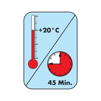
| ≥ +20 °C2) | 6 min | 45 min | 90 min |
| ≥ +30 °C2) | 4 min | 25 min | 50 min |
| ≥ +35 °C2) | 2 min | 20 min | 40 min |
| ≥ +40 °C3) | 1.5 min | 15 min | 30 min |
| 1) Cartridge temperature: ≥ +15 °C 2) Cartridge temperature: +5 °C to +25 °C 3) Cartridge temperature: < 20 °C | |||
| Minimum curing times in masonry | |||
| Temperature of base material | Processing time | Minimum curing time in dry masonry | Minimum curing time in wet masonry |
| -10 °C to -6 °C1) | 90 min | 24 h | 48 h |
| -5 °C to -1 °C2) | 90 min | 14 h | 28 h |
| 0 °C to +4 °C2) | 45 min | 7 h | 14 h |
| +5 °C to +9 °C2) | 25 min | 2 h | 4 h |
| +10 °C to +19 °C2) | 15 min | 80 min | 160 min |
| +20 °C to +24 °C2) | 6 min | 45 min | 90 min |
| +25 °C to +29 °C2) | 4 min | 25 min | 50 min |
| +30 °C to +40 °C3) | 2.5 min | 15 min | 30 min |
| 1) Cartridge temperature: ≥ +15 °C 2) Cartridge temperature: +5 °C to +25 °C 3) Cartridge temperature: < +20 °C | |||
- European Technical Assessment ETA-12/0164: Individual fixing point + cracked and uncracked concrete (W-VD-A anchor rod, standard threaded rod with 3.1 acceptance test certificate), seismic performance category C1
- European Technical Assessment ETA-13/1040: Individual fixing point + masonry consisting of solid and perforated block, autoclaved aerated concrete (WIT-SH perforated sleeve, WIT-AS anchor rod, WIT-IG internally threaded sleeve, autoclaved aerated concrete only with WIT-SH 18x95 perforated sleeve)
- European Technical Assessment ETA-16/0757 and ETA-20/0854: Individual fixing point + masonry consisting of solid and perforated block, autoclaved aerated concrete (SH perforated sleeve, W-VI-A anchor rod, W-VI-IG internal thread anchor, threaded rod with acceptance test certificate 3.1, autoclaved aerated concrete only without perforated sleeve)
- European Technical Assessment ETA-12/0166: Post-installed rebar connection, 330 ml, 420 ml and 825 ml cartridges only
- EPD: Environmental product declaration in accordance with ISO 14025 and EN 15804+A2, EPD-AWU-20230406-CBA3
Datasheets(X)

- Anchoring in cracked and uncracked concrete, masonry laid with solid and perforated block, autoclaved aerated concrete and for post-installed rebars.
- Suitable for mounting metal structures, metal sections, wooden structures, brackets, grates, pipes, cable conduits etc.
A 330 ml and 420 ml cartridge can continue to be used until the best before date, by changing the mixer nozzle or resealing it with the end cap.
Type description | WIT-VM 250 |
Contents | 330 ml |
Included in delivery | Mortar cartridge 330 ml (coaxial) + 1 x mixer nozzle |
Suitable application gun | Battery-powered application gun 330ml, Application gun WIT 330ml, HandyMax 330 ml, Application gun MULTI, EasyMax 330 ml |
Min./max. processing temperature /conditions | -10 to 40 °C / temperature in the anchorage ground during processing and hardening |
Min./max. ambient temperature / Conditions | -40 to 120 °C / after completely curing process |
Temperature resistance, long-term temperatures max. | 72 °C |
Temperature resistance, short-term temperatures max. | 120 °C |
Shelf life from production/conditions | 18 Month / cool and dry storage area, 5°C to 25°C |
Approval | ETA-12/0164, ETA-13/1040, ETA-12/0166, ETA-16/0757, ETA-20/0854 |
Chemical basis | Vinylester, styrene free |
Colour | Grey |
| Performance data: Perforated block masonry with perforated sleeve | |||||||||||||
| Individual fixing point (dry masonry, temperature range 50 °C1)/80 °C2)) Other minimum compressive strengths, temperature ranges (24 °C1)/40 °C2); 72 °C1)/120 °C2)), wet masonry, edge distances and spacings can be found in the European Technical Assessment ETA-16/0757 | Anchor size | Brick compressive strength [N/mm²] | Brick density [kg/dm3] | Brick format6) [mm] | Effective anchorage depth hef [mm] | Minimum member thickness hmin [mm] | Maximum installation torque Tinst,max [Nm] | Admissible tensile load3)4)5) (individual anchor without influence of the edge distance) Nadm [kN] | Admissible shear load3)4)5) (individual anchor without influence of the edge distance) Vadm [kN] | Char. spacing parallel to bed joint4) scr || [mm] | Char. spacing perpendicular to bed joint4) scr ⊥ [mm] | Minimum spacing 4) smin [mm] | Char. edge distance ccr [mm] | Minimum edge distance4) cmin [mm] |
| Vertically perforated brick HLz-16DF EN 771-1 | |||||||||||||
| M12 Perforated sleeve 20x130 | 6 | 0,83 | 497 x 240 x 238 | 130 | 195 | 2 | 1,0 | 1,71 | 500 | 240 | 100 | 120 | 120 |
| 8 | 1,29 | 2,0 | |||||||||||
| 12 | 1,43 | 2,57 | |||||||||||
| 14 | 1,57 | 2,57 | |||||||||||
| M12 Perforated sleeve 20x200 | 6 | 200 | 240 | 1,0 | 1,71 | ||||||||
| 8 | 1,29 | 2,0 | |||||||||||
| 12 | 1,43 | 2,57 | |||||||||||
| 14 | 1,57 | 2,57 | |||||||||||
| M16/IT M10 Perforated sleeve 20x85 | 6 | 85 | 115 | 0,71 | 1,43 | ||||||||
| 8 | 0,86 | 1,71 | |||||||||||
| 12 | 1,0 | 2,0 | |||||||||||
| 14 | 1,14 | 2,0 | |||||||||||
| M16 Perforated sleeve 20x130 | 6 | 130 | 195 | 1,0 | 1,71 | ||||||||
| 8 | 1,29 | 2,0 | |||||||||||
| 12 | 1,43 | 2,57 | |||||||||||
| 14 | 1,57 | 2,57 | |||||||||||
| M16 Perforated sleeve 20x200 | 6 | 200 | 240 | 1,0 | 1,71 | ||||||||
| 8 | 1,29 | 2,0 | |||||||||||
| 12 | 1,43 | 2,57 | |||||||||||
| 14 | 1,57 | 2,57 | |||||||||||
| Hollow sand-lime block KS L-3DF EN 771-2 | |||||||||||||
| M8 Perforated sleeve 12x80 | 8 | 1,4 | 240 x 175 x 113 | 80 | 115 | 2 | 0,43 | 0.717)/0.288) | 240 | 120 | 120 | 100 | 60 |
| 12 | 0,57 | 1.147)/0.438) | |||||||||||
| 14 | 0,71 | 1.07)/0.438) | |||||||||||
| M8 Perforated sleeve 16x85 | 8 | 85 | 115 | 8 | 0,43 | 1.147)/0.438) | |||||||
| 12 | 0,57 | 1.147)/0.438) | |||||||||||
| 14 | 0,71 | 1.717)/0.578) | |||||||||||
| M8 Perforated sleeve 16x130 | 8 | 130 | 195 | 0,43 | 1.147)/0.438) | ||||||||
| 12 | 0,71 | 1.147)/0.438) | |||||||||||
| 14 | 0,71 | 1.717)/0.578) | |||||||||||
| M10/IT M6 Perforated sleeve 16x85 | 8 | 85 | 115 | 0,43 | 1.147)/0.438) | ||||||||
| 12 | 0,57 | 1.147)/0.438) | |||||||||||
| 14 | 0,71 | 1.717)/0.578) | |||||||||||
| M10 Perforated sleeve 16x130 | 8 | 130 | 195 | 0,43 | 1.147)/0.438) | ||||||||
| 12 | 0,71 | 1.147)/0.438) | |||||||||||
| 14 | 0,71 | 1.717)/0.578) | |||||||||||
| M12/IT M8 Perforated sleeve 20x85 | 8 | 85 | 115 | 1,14 | 1.147)/0.438) | 120 | |||||||
| 12 | 1,57 | 1.147)/0.438) | |||||||||||
| 14 | 1,71 | 1.717)/0.578) | |||||||||||
| M12 Perforated sleeve 20x130 | 8 | 130 | 195 | 1,14 | 1.147)/0.438) | ||||||||
| 12 | 1,57 | 1.147)/0.438) | |||||||||||
| 14 | 1,71 | 1.717)/0.578) | |||||||||||
| 1) Maximum long-term temperature 2) Maximum short-term temperature 3) The partial safety factors of the resistances regulated in the approval and ETAG 029 and a partial safety factor of the actions of γF = 1.4 have been taken into account. 4) If the characteristic spacing and edge distances are reduced, the admissible loads must also be reduced. The smallest possible spacing or edge distance is the minimum spacing smin or minimum edge distance cmin 5) For combinations of tensile and shear loads, bending moments or reduced edge distances and spacings, see the European Technical Assessment. If the masonry joints are not visible, the load capacity should be reduced by a factor of αj = 0.75. If the masonry joints are visible (e.g. on an unplastered wall) the following should be observed: 1. The load capacity may only be assessed when the masonry joint is filled with mortar. 2. If the masonry joints are not filled with mortar, the load capacity may only be assessed if the minimum edge distance cmin to the perpend joints has been adhered to. If this minimum edge distance cmin is not adhered to, the load capacity should be reduced by a factor of αj = 0.75. Documentation for brick removal must also be supplied in accordance with ETAG 029 Annex C. 6) The brick and hole geometry must be found in the European Technical Assessment. 7) Nadm or Vadm applies for the edge distance ccr, clip value (Nadm) or (Vadm) applies for the minimum edge distance (cmin). | |||||||||||||
| Performance data: Solid and perforated block masonry with perforated sleeve | |||||||||||||
| Individual fixing point (dry masonry, temperature range 50 °C1)/80 °C2)) Other minimum compressive strengths, temperature ranges (24 °C1)/40 °C2); 72 °C1)/120 °C2)), wet masonry, edge distances and spacings can be found in the European Technical Assessment ETA-16/0757 | |||||||||||||
| Anchor size | Brick compressive strength [N/mm²] | Brick density [kg/dm³] | Brick format6) [mm] | Minimum member thickness hmin [mm] | Effective anchorage depth hef [mm] | Maximum installation torque Tinst,max [Nm] | Admissible tensile load3)4)5) (individual anchor without influence of the edge distance) Nadm [kN] | Admissible shear load3)4)5) (individual anchor without influence of the edge distance) Vadm [kN] | Char. spacing parallel to bed joint4) scr || [mm] | Char. spacing perpendicular to bed joint4) scr ⊥ [mm] | Minimum spacing 4) smin [mm] | Char. edge distance ccr [mm] | Minimum edge distance4) cmin [mm] |
| Lightweight solid concrete block Vbl EN 771-3 | |||||||||||||
| M12/IT M8 Perforated sleeve 20x85 | 2 | 0,63 | 300 x 123 x 248 | 115 | 85 | 2 | 0,71 | 0,86 | 255 | 255 | 120 | 127,5 | 60 |
| M12 Perforated sleeve 20x130 | 195 | 130 | 0,71 | 0,86 | 390 | 390 | 195 | ||||||
| M12 Perforated sleeve 20x200 | 240 | 200 | 0,71 | 0,86 | 600 | 600 | 300 | ||||||
| M16/IT M10 Perforated sleeve 20x85 | 115 | 85 | 0,71 | 0,86 | 255 | 255 | 127,5 | ||||||
| M16 Perforated sleeve 20x130 | 195 | 130 | 0,71 | 0,86 | 390 | 390 | 195 | ||||||
| M16 Perforated sleeve 20x200 | 240 | 200 | 0,71 | 0,86 | 600 | 600 | 300 | ||||||
| Vertically perforated brick HLz-16DF EN 771-1 | |||||||||||||
| M8 Perforated sleeve 12x80 | 6 | 0,83 | 497 x 240 x 238 | 115 | 80 | 2 | 0,71 | 0,71 | 500 | 240 | 100 | 100 | 100 |
| 8 | 0,86 | 0,86 | |||||||||||
| 12 | 1,0 | 1,14 | |||||||||||
| 14 | 1,14 | 1,14 | |||||||||||
| M8 Perforated sleeve 16x85 | 6 | 115 | 85 | 0,71 | 1,29 | ||||||||
| 8 | 0,86 | 1,57 | |||||||||||
| 12 | 1,0 | 1,86 | |||||||||||
| 14 | 1,14 | 1,86 | |||||||||||
| M8 Perforated sleeve 16x130 | 6 | 195 | 130 | 1,0 | 1,29 | ||||||||
| 8 | 1,29 | 1,57 | |||||||||||
| 12 | 1,43 | 1,86 | |||||||||||
| 14 | 1,57 | 1,86 | |||||||||||
| M10 Perforated sleeve 16x85 | 6 | 115 | 85 | 0,71 | 1,29 | ||||||||
| 8 | 0,86 | 1,57 | |||||||||||
| 12 | 1,0 | 1,86 | |||||||||||
| 14 | 1,14 | 1,86 | |||||||||||
| M10 Perforated sleeve 16x130 | 6 | 195 | 130 | 1,0 | 1,29 | ||||||||
| 8 | 1,29 | 1,57 | |||||||||||
| 12 | 1,43 | 1,86 | |||||||||||
| 14 | 1,57 | 1,86 | |||||||||||
| M12 Perforated sleeve 20x85 | 6 | 115 | 85 | 0,71 | 1,43 | 120 | 120 | ||||||
| 8 | 0,86 | 1,71 | |||||||||||
| 12 | 1,0 | 2,0 | |||||||||||
| 14 | 1,14 | 2,0 | |||||||||||
| 1) Maximum long-term temperature 2) Maximum short-term temperature 3) The partial safety factors of the resistances regulated in the approval and ETAG 029 and a partial safety factor of the actions of γF = 1.4 have been taken into account. 4) If the characteristic spacing and edge distances are reduced, the admissible loads must also be reduced. The smallest possible spacing or edge distance is the minimum spacing smin or minimum edge distance cmin. 5) For combinations of tensile and shear loads, bending moments or reduced edge distances and spacings, see the European Technical Assessment. If the masonry joints are not visible, the load capacity should be reduced by a factor of αj = 0.75. If the masonry joints are visible (e.g. on an unplastered wall) the following should be observed: 1. The load capacity may only be assessed when the masonry joint is filled with mortar. 2. If the masonry joints are not filled with mortar, the load capacity may only be assessed if the minimum edge distance cmin to the perpend joints has been adhered to. If this minimum edge distance cmin is not adhered to, the load capacity should be reduced by a factor of αj = 0.75. Documentation for brick removal must also be supplied in accordance with ETAG 029 Annex C. 6) The brick and hole geometry must be found in the European Technical Assessment. 7) Nadm or Vadm applies for the edge distance ccr, clip value (Nadm) or (Vadm) applies for the minimum edge distance (cmin). | |||||||||||||
| Performance data: Solid block masonry without perforated sleeve | |||||||||||||
| Individual fixing point (dry masonry, temperature range 50 °C1)/80 °C2)) Other minimum compressive strengths, temperature ranges (24 °C1)/40 °C2); 72 °C1)/120 °C2)), wet masonry, edge distances and spacings can be found in European Technical Assessment A-16/0757 | Anchor size | Brick compressive strength [N/mm²] | Brick density [kg/dm³] | Brick format6) [mm] | Effective anchorage depth hef [mm] | Minimum member thickness hmin [mm] | Maximum installation torque Tinst,max [Nm] | Admissible tensile load3)4)5) (individual anchor without influence of the edge distance) Nadm [kN] | Admissible shear load3)4)5) (individual anchor without influence of the edge distance) Vadm [kN] | Char. spacing parallel to bed joint4) scr || [mm] | Char. spacing perpendicular to bed joint4) scr ⊥ [mm] | Minimum spacing 4) smin [mm] | Char. edge distance ccr [mm] | Minimum edge distance4) cmin [mm] |
| Solid sand-lime block KS-NF EN 771-2 | |||||||||||||
| M10/IT M6 Perforated sleeve 16x85 | 10 | 2,0 | 240 x 115 x 71 | 85 | 115 | 2 | 0.86 (0.43)7) | 0.71 (0.43)7) | 255 | 255 | 120 | 127,5 | (60)7) |
| 20 | 2,0 | 240 x 115 x 71 | 2 | 1.29 (0.57)7) | 1.14 (0.71)7) | (60)7) | |||||||
| 27 | 2,0 | 240 x 115 x 71 | 2 | 1.43 (0.71)7) | 1.29 (0.71)7) | (60)7) | |||||||
| M10 Perforated sleeve 16x130 | 10 | 2,0 | 240 x 115 x 71 | 130 | 195 | 2 | 0.86 (0.43)7) | 0.71 (0.43)7) | 390 | 390 | 120 | 195 | (60)7) |
| 20 | 2,0 | 240 x 115 x 71 | 2 | 1.29 (0.57)7) | 1.14 (0.71)7) | (60)7) | |||||||
| 27 | 2,0 | 240 x 115 x 71 | 2 | 1.43 (0.71)7) | 1.29 (0.71)7) | (60)7) | |||||||
| M12/IT M8 Perforated sleeve 20x85 | 10 | 2,0 | 240 x 115 x 71 | 85 | 115 | 2 | 0.71 (0.34)7) | 0.71 (0.43)7) | 255 | 255 | 120 | 127,5 | (60)7) |
| 20 | 2,0 | 240 x 115 x 71 | 2 | 1.14 (0.57)7) | 1.14 (0.71)7) | (60)7) | |||||||
| 27 | 2,0 | 240 x 115 x 71 | 2 | 1.29 (0.57)7) | 1.29 (0.71)7) | (60)7) | |||||||
| M12 Perforated sleeve 20x130 | 10 | 2,0 | 240 x 115 x 71 | 130 | 195 | 2 | 0.71 (0.34)7) | 0.71 (0.43)7) | 390 | 390 | 120 | 195 | (60)7) |
| 20 | 2,0 | 240 x 115 x 71 | 2 | 1.14 (0.57)7) | 1.14 (0.71)7) | (60)7) | |||||||
| 27 | 2,0 | 240 x 115 x 71 | 2 | 1.29 (0.57)7) | 1.29 (0.71)7) | (60)7) | |||||||
| M12 Perforated sleeve 20x200 | 10 | 2,0 | 240 x 115 x 71 | 200 | 240 | 2 | 0.71 (0.34)7) | 0.71 (0.43)7) | 600 | 600 | 120 | 300 | (60)7) |
| 20 | 2,0 | 240 x 115 x 71 | 2 | 1.14 (0.57)7) | 1.14 (0.71)7) | (60)7) | |||||||
| 27 | 2,0 | 240 x 115 x 71 | 2 | 1.29 (0.57)7) | 1.29 (0.71)7) | (60)7) | |||||||
| M16/IT M10 Perforated sleeve 20x85 | 10 | 2,0 | 240 x 115 x 71 | 85 | 115 | 2 | 0.71 (0.34)7) | 0.71 (0.43)7) | 255 | 255 | 120 | 127,5 | (60)7) |
| 20 | 2,0 | 240 x 115 x 71 | 2 | 1.14 (0.57)7) | 1.14 (0.71)7) | (60)7) | |||||||
| 27 | 2,0 | 240 x 115 x 71 | 2 | 1.29 (0.57)7) | 1.29 (0.71)7) | (60)7) | |||||||
| M16 Perforated sleeve 20x130 | 10 | 2,0 | 240 x 115 x 71 | 130 | 195 | 2 | 0.71 (0.34)7) | 0.71 (0.43)7) | 390 | 390 | 120 | 195 | (60)7) |
| 20 | 2,0 | 240 x 115 x 71 | 2 | 1.14 (0.57)7) | 1.14 (0.71)7) | (60)7) | |||||||
| 27 | 2,0 | 240 x 115 x 71 | 2 | 1.29 (0.57)7) | 1.29 (0.71)7) | (60)7) | |||||||
| M16 Perforated sleeve 20x200 | 10 | 2,0 | 240 x 115 x 71 | 200 | 240 | 2 | 0.71 (0.34)7) | 0.71 (0.43)7) | 600 | 600 | 120 | 300 | (60)7) |
| 20 | 2,0 | 240 x 115 x 71 | 2 | 1.14 (0.57)7) | 1.14 (0.71)7) | (60)7) | |||||||
| 27 | 2,0 | 240 x 115 x 71 | 2 | 1.29 (0.57)7) | 1.29 (0.71)7) | (60)7) | |||||||
| Lightweight solid concrete block Vbl EN 771-3 | |||||||||||||
| M8 Perforated sleeve 12x80 | 2 | 0,63 | 300 x 123 x 248 | 80 | 115 | 2 | 0,71 | 0,86 | 240 | 240 | 120 | 120 | 60 |
| M8 Perforated sleeve 16x85 | 85 | 115 | 0,71 | 0,86 | 255 | 255 | 127,5 | ||||||
| M8 Perforated sleeve 16x130 | 130 | 195 | 0,71 | 0,86 | 390 | 390 | 195 | ||||||
| M10/IT M6 Perforated sleeve 16x85 | 85 | 115 | 0,71 | 0,86 | 255 | 255 | 127,5 | ||||||
| M10 Perforated sleeve 16x130 | 130 | 195 | 0,71 | 0,86 | 390 | 390 | 195 | ||||||
| 1) Maximum long-term temperature 2) Maximum short-term temperature 3) The partial safety factors of the resistances regulated in the approval and ETAG 029 and a partial safety factor of the actions of γF = 1.4 have been taken into account. 4) If the characteristic spacing and edge distances are reduced, the admissible loads must also be reduced. The smallest possible spacing or edge distance is the minimum spacing smin or minimum edge distance cmin 5) For combinations of tensile and shear loads, bending moments or reduced edge distances and spacings, see the European Technical Assessment. If the masonry joints are not visible, the load capacity should be reduced by a factor of αj = 0.75. If the masonry joints are visible (e.g. on an unplastered wall) the following should be observed: 1. The load capacity may only be assessed when the masonry joint is filled with mortar. 2. If the masonry joints are not filled with mortar, the load capacity may only be assessed if the minimum edge distance cmin to the perpend joints has been adhered to. If this minimum edge distance cmin is not adhered to, the load capacity should be reduced by a factor of αj = 0.75. Documentation for brick removal must also be supplied in accordance with ETAG 029 Annex C. 6) The brick and hole geometry must be found in the European Technical Assessment. 7) Nadm or Vadm applies for the edge distance ccr, clip value (Nadm) or (Vadm) applies for the minimum edge distance (cmin). | |||||||||||||
| Performance data: Solid block masonry without perforated sleeve | |||||||||||||
| Individual fixing point (dry masonry, temperature range 50 °C1)/80 °C2)) Other minimum compressive strengths, temperature ranges (24 °C1)/40 °C2); 72 °C1)/120 °C2)), wet masonry, edge distances and spacings can be found in the European Technical Assessment ETA-16/0757 | |||||||||||||
| Anchor size | Brick compressive strength [N/mm²] | Brick density [kg/dm³] | Brick format6) [mm] | Effective anchorage depth hef [mm] | Minimum member thickness hmin [mm] | Maximum installation torque Tinst,max [Nm] | Admissible tensile load3)4)5) (individual anchor without influence of the edge distance) Nadm [kN] | Admissible shear load3)4)5) (individual anchor without influence of the edge distance) Vadm [kN] | Char. spacing parallel to bed joint4) scr || [mm] | Char. spacing perpendicular to bed joint4) scr ⊥ [mm] | Minimum spacing 4) smin [mm] | Char. edge distance ccr [mm] | Minimum edge distance4) cmin [mm] |
| Solid brick Mz-DF EN 771-1 | |||||||||||||
| M8 Perforated sleeve 12x80 | 10 | 1,64 | 240 x 115 x 55 | 80 | 115 | 2 | 1.0 (0.43)7) | 1.0 (0.34)7) | 240 | 240 | 120 | 120 | (60)7) |
| 20 | 1,64 | 240 x 115 x 55 | 2 | 1.29 (0.71)7) | 1.43 (0.43)7) | ||||||||
| 28 | 1,64 | 240 x 115 x 55 | 2 | 1.57 (0.71)7) | 1.57 (0.57)7) | ||||||||
| M8 Perforated sleeve 16x85 | 10 | 1,64 | 240 x 115 x 55 | 85 | 115 | 2 | 1.0 (0.43)7) | 1.0 (0.34)7) | 255 | 255 | 120 | 127,5 | (60)7) |
| 20 | 1,64 | 240 x 115 x 55 | 2 | 1.43 (0.71)7) | 1.43 (0.43)7) | ||||||||
| 28 | 1,64 | 240 x 115 x 55 | 2 | 1.71 (0.86)7) | 1.57 (0.57)7) | ||||||||
| M8 Perforated sleeve 16x130 | 10 | 1,64 | 240 x 115 x 55 | 130 | 195 | 2 | 1.0 (0.43)7) | 1.0 (0.34)7) | 390 | 390 | 120 | 195 | (60)7) |
| 20 | 1,64 | 240 x 115 x 55 | 2 | 1.43 (0.71)7) | 1.43 (0.43)7) | ||||||||
| 28 | 1,64 | 240 x 115 x 55 | 2 | 1.71 (0.86)7) | 1.57 (0.57)7) | ||||||||
| M10/IT M6 Perforated sleeve 16x85 | 10 | 1,64 | 240 x 115 x 55 | 85 | 115 | 2 | 1.0 (0.43)7) | 1.0 (0.43)7) | 255 | 255 | 120 | 127,5 | (60)7) |
| 20 | 1,64 | 240 x 115 x 55 | 2 | 1.43 (0.71)7) | 1.43 (0.43)7) | ||||||||
| 28 | 1,64 | 240 x 115 x 55 | 2 | 1.71 (0.86)7) | 1.57 (0.57)7) | ||||||||
| M10 Perforated sleeve 16x130 | 10 | 1,64 | 240 x 115 x 55 | 130 | 195 | 2 | 1.0 (0.43)7) | 1.0 (0.43)7) | 390 | 390 | 120 | 195 | (60)7) |
| 20 | 1,64 | 240 x 115 x 55 | 2 | 1.43 (0.71)7) | 1.43 (0.43)7) | ||||||||
| 27 | 1,64 | 240 x 115 x 55 | 2 | 1.71 (0.86)7) | 1.57 (0.57)7) | ||||||||
| M12/IT M8 Perforated sleeve 20x85 | 10 | 1,64 | 240 x 115 x 55 | 85 | 115 | 2 | 1.0 (0.43)7) | 1.0 (0.43)7) | 255 | 255 | 120 | 127,5 | (60)7) |
| 20 | 1,64 | 240 x 115 x 55 | 2 | 1.43 (0.71)7) | 1.43 (0.43)7) | ||||||||
| 27 | 1,64 | 240 x 115 x 55 | 2 | 1.71 (0.86)7) | 1.57 (0.57)7) | ||||||||
| M12 Perforated sleeve 20x130 | 10 | 1,64 | 240 x 115 x 55 | 130 | 195 | 2 | 1.0 (0.43)7) | 1.0 (0.43)7) | 390 | 390 | 120 | 195 | (60)7) |
| 20 | 1,64 | 240 x 115 x 55 | 2 | 1.43 (0.71)7) | 1.43 (0.43)7) | ||||||||
| 27 | 1,64 | 240 x 115 x 55 | 2 | 1.71 (0.86)7) | 1.57 (0.57)7) | ||||||||
| M12 Perforated sleeve 20x200 | 10 | 1,64 | 240 x 115 x 55 | 200 | 240 | 2 | 1.0 (0.43)7) | 1.0 (0.43)7) | 600 | 600 | 120 | 300 | (60)7) |
| 20 | 1,64 | 240 x 115 x 55 | 2 | 1.43 (0.71)7) | 1.43 (0.43)7) | ||||||||
| 27 | 1,64 | 240 x 115 x 55 | 2 | 1.71 (0.86)7) | 1.57 (0.57)7) | ||||||||
| M16/IT M10 Perforated sleeve 20x85 | 10 | 1,64 | 240 x 115 x 55 | 85 | 115 | 2 | 1.0 (0.43)7) | 1.0 (0.43)7) | 255 | 255 | 120 | 127,5 | (60)7) |
| 20 | 1,64 | 240 x 115 x 55 | 2 | 1.43 (0.71)7) | 1.43 (0.43)7) | ||||||||
| 28 | 1,64 | 240 x 115 x 55 | 2 | 1.71 (0.86)7) | 1.57 (0.57)7) | ||||||||
| M16 Perforated sleeve 20x130 | 10 | 1,64 | 240 x 115 x 55 | 130 | 195 | 2 | 1.0 (0.43)7) | 1.0 (0.43)7) | 390 | 390 | 120 | 195 | (60)7) |
| 20 | 1,64 | 240 x 115 x 55 | 2 | 1.43 (0.71)7) | 1.43 (0.43)7) | ||||||||
| 28 | 1,64 | 240 x 115 x 55 | 2 | 1.71 (0.86)7) | 1.57 (0.57)7) | ||||||||
| M16 Perforated sleeve 20x200 | 10 | 1,64 | 240 x 115 x 55 | 200 | 240 | 2 | 1.0 (0.43)7) | 1.0 (0.43)7) | 600 | 600 | 120 | 300 | (60)7) |
| 20 | 1,64 | 240 x 115 x 55 | 2 | 1.43 (0.71)7) | 1.43 (0.43)7) | ||||||||
| 28 | 1,64 | 240 x 115 x 55 | 2 | 1.71 (0.86)7) | 1.57 (0.57)7) | ||||||||
| Solid sand-lime block KS-NF EN 771-2 | |||||||||||||
| M8 Perforated sleeve 12x80 | 10 | 2,0 | 240 x 115 x 71 | 80 | 115 | 2 | 1.0 (0.43)7) | 0.71 (0.43)7) | 240 | 240 | 120 | 120 | (60)7) |
| 20 | 1.43 (0.71)7) | 1.14 (0.71)7) | |||||||||||
| 27 | 1.71 (0.86)7) | 1.29 (0.71)7) | |||||||||||
| M8 Perforated sleeve 16x85 | 10 | 85 | 115 | 0.86 (0.43)7) | 0.71 (0.43)7) | 255 | 255 | 120 | 127,5 | (60)7) | |||
| 20 | 1.29 (0.57)7) | 1.14 (0.71)7) | |||||||||||
| 27 | 1.43 (0.71)7) | 1.29 (0.71)7) | |||||||||||
| M8 Perforated sleeve 16x130 | 10 | 130 | 195 | 0.86 (0.43)7) | 0.71 (0.43)7) | 390 | 390 | 120 | 195 | (60)7) | |||
| 20 | 1.29 (0.57)7) | 1.14 (0.71)7) | |||||||||||
| 27 | 1.43 (0.71)7) | 1.29 (0.71)7) | |||||||||||
| 1) Maximum long-term temperature 2) Maximum short-term temperature 3) The partial safety factors of the resistances regulated in the approval and ETAG 029 and a partial safety factor of the actions of γF = 1.4 have been taken into account. 4) If the characteristic spacing and edge distances are reduced, the admissible loads must also be reduced. The smallest possible spacing or edge distance is the minimum spacing smin or minimum edge distance cmin. 5) For combinations of tensile and shear loads, bending moments or reduced edge distances and spacings, see the European Technical Assessment. If the masonry joints are not visible, the load capacity should be reduced by a factor of αj = 0.75. If the masonry joints are visible (e.g. on an unplastered wall) the following should be observed: 1. The load capacity may only be assessed when the masonry joint is filled with mortar. 2. If the masonry joints are not filled with mortar, the load capacity may only be assessed if the minimum edge distance cmin to the perpend joints has been adhered to. If this minimum edge distance cmin is not adhered to, the load capacity should be reduced by a factor of αj = 0.75. Documentation for brick removal must also be supplied in accordance with ETAG 029 Annex C. 6) The brick and hole geometry must be taken from the European Technical Assessment. 7) Nadm or Vadm applies for the edge distance ccr, clip value (Nadm) or (Vadm) applies for the minimum edge distance (cmin). | |||||||||||||
| Cracked and uncracked concrete: Performance data and installation parameters | ||||||||||||||
| Temperature range: 24 °C1)/40 °C2) (temperature ranges 50 °C/80 °C and 72 °C/120 °C; see ETA-12/0164) Base material: Dry and wet concrete (base material: water-filled drill hole; see ETA-12/0164) Concrete compressive strength: C20/25 (C25/30 to C50/60 see ETA-12/0164, without congested reinforcement) | ||||||||||||||
| Anchor diameter | M8 | M10 | M12 | M16 | ||||||||||
| Effective anchorage depth | hef [mm] | 60 | 80 | 160 | 60 | 90 | 200 | 70 | 110 | 240 | 80 | 125 | 320 | |
| Cracked concrete | ||||||||||||||
| Admissible centric tension load3) (individual anchor without the influence of the edge distance) | Zinc-plated steel, 5.8 | Nadm [kN] | 2,4 | 3,2 | 6,4 | 3,7 | 5,6 | 12,5 | 5,8 | 9,1 | 19,7 | 8,8 | 13,7 | 35,1 |
| Zinc-plated steel, 8.8 | Nadm [kN] | 2,4 | 3,2 | 6,4 | 3,7 | 5,6 | 12,5 | 5,8 | 9,1 | 19,7 | 8,8 | 13,7 | 35,1 | |
| A4 and HCR stainless steel | Nadm [kN] | 2,4 | 3,2 | 6,4 | 3,7 | 5,6 | 12,5 | 5,8 | 9,1 | 19,7 | 8,8 | 13,7 | 35,1 | |
| Admissible shear load3) (individual anchor without the influence of the edge distance) | Zinc-plated steel, 5.8 | Vadm [kN] | 5,1 | 5,1 | 5,1 | 8,6 | 8,6 | 8,6 | 12,0 | 12,0 | 12,0 | 21,1 | 22,3 | 22,3 |
| Zinc-plated steel, 8.8 | Vadm [kN] | 5,7 | 7,7 | 8,6 | 9,0 | 13,1 | 13,1 | 13,8 | 19,4 | 19,4 | 21,1 | 32,0 | 36,0 | |
| A4 and HCR stainless steel | Vadm [kN] | 5,7 | 6,0 | 6,0 | 9,0 | 9,2 | 9,2 | 13,7 | 13,7 | 13,7 | 21,1 | 25,2 | 25,2 | |
| Uncracked concrete | ||||||||||||||
| Admissible centric tension load3) (individual anchor without the influence of the edge distance) | Zinc-plated steel, 5.8 | Nadm [kN] | 7,2 | 8,6 | 8,6 | 9,0 | 13,4 | 13,8 | 11,7 | 19,7 | 20,0 | 14,4 | 28,0 | 37,1 |
| Zinc-plated steel, 8.8 | Nadm [kN] | 7,2 | 9,6 | 13,8 | 9,0 | 13,4 | 21,9 | 11,7 | 19,7 | 31,9 | 14,4 | 28,0 | 59,5 | |
| A4 and HCR stainless steel | Nadm [kN] | 7,2 | 9,6 | 9,9 | 9,0 | 13,4 | 15,7 | 11,7 | 19,7 | 22,5 | 14,4 | 28,0 | 42,0 | |
| Admissible shear load3) (individual anchor without the influence of the edge distance) | Zinc-plated steel, 5.8 | Vadm [kN] | 5,1 | 5,1 | 5,1 | 8,6 | 8,6 | 8,6 | 12,0 | 12,0 | 12,0 | 22,3 | 22,3 | 22,3 |
| Zinc-plated steel, 8.8 | Vadm [kN] | 8,6 | 8,6 | 8,6 | 13,1 | 13,1 | 13,1 | 19,4 | 19,4 | 19,4 | 30,6 | 36,0 | 36,0 | |
| A4 and HCR stainless steel | Vadm [kN] | 6,0 | 6,0 | 6,0 | 9,2 | 9,2 | 9,2 | 13,7 | 13,7 | 13,7 | 25,2 | 25,2 | 25,2 | |
| Nominal drill dia. | d0 [mm] | 10 | 12 | 14 | 18 | |||||||||
| Drill hole depth/effective anchorage depth | h0/hef [mm] | 60 | 80 | 160 | 60 | 90 | 200 | 70 | 110 | 240 | 80 | 125 | 320 | |
| Minimum edge distance | cmin [mm] | 40 | 50 | 60 | 80 | |||||||||
| Minimum spacing | smin [mm] | 40 | 50 | 60 | 80 | |||||||||
| Minimum member thickness | hmin [mm] | 100 | 110 | 190 | 100 | 120 | 230 | 100 | 140 | 270 | 116 | 161 | 356 | |
| Through hole in the member being connected | df ≤ [mm] | 9 | 12 | 14 | 18 | |||||||||
| Torque while installing anchor | Tinst ≤ [Nm] | 10 | 20 | 40 | 80 | |||||||||
| 1) Maximum long-term temperature 2) Maximum short-term temperature 3) The partial safety factors of the resistances regulated in the approval and a partial safety factor of the actions of γF = 1.4 have been taken into account. Please refer to the EOTA Technical Report TR 029 "Design of Bonded Anchors" for information on combining tensile and shear loads, the influence of the edge distance and groups of anchors. | ||||||||||||||
| Performance data: Perforated block masonry with perforated sleeve | |||||||||||||
| Individual fixing point (dry masonry, temperature range 50 °C1)/80 °C2)) Other minimum compressive strengths, temperature ranges (24 °C1)/40 °C2); 72 °C1)/120 °C2)), wet masonry, edge distances and spacings can be found in the European Technical Assessment ETA-16/0757 | Anchor size | Brick compressive strength [N/mm²] | Brick density [kg/dm³] | Brick format6) [mm] | Effective anchorage depth hef [mm] | Minimum member thickness hmin [mm] | Maximum installation torque Tinst,max [Nm] | Admissible tensile load3)4)5) (individual anchor without influence of the edge distance) Nadm [kN] | Admissible shear load3)4)5) (individual anchor without influence of the edge distance) Vadm [kN] | Char. spacing parallel to bed joint4) scr || [mm] | Char. spacing perpendicular to bed joint4) scr ⊥ [mm] | Minimum spacing 4) smin [mm] | Char. edge distance ccr [mm] | Minimum edge distance4) cmin [mm] |
| Hollow sand-lime block KS L-3DF EN 771-2 | |||||||||||||
| M12 Perforated sleeve 20x200 | 8 | 1,4 | 240 x 175 x 113 | 200 | 240 | 2 | 1,14 | 1.147)/0.438) | 240 | 120 | 120 | 120 | 60 |
| 12 | 1,57 | 1.147)/0.438) | |||||||||||
| 14 | 1,71 | 1.717)/0.578) | |||||||||||
| M16/IT M10 Perforated sleeve 20x85 | 8 | 85 | 115 | 1,14 | 1.147)/0.438) | ||||||||
| 12 | 1,57 | 1.147)/0.438) | |||||||||||
| 14 | 1,71 | 1.717)/0.578) | |||||||||||
| M16 Perforated sleeve 20x130 | 8 | 130 | 195 | 1,14 | 1.147)/0.438) | ||||||||
| 12 | 1,57 | 1.147)/0.438) | |||||||||||
| 14 | 1,71 | 1.717)/0.578) | |||||||||||
| M16 Perforated sleeve 20x200 | 8 | 200 | 240 | 1,14 | 1.147)/0.438) | ||||||||
| 12 | 1,57 | 1.147)/0.438) | |||||||||||
| 14 | 1,71 | 1.717)/0.578) | |||||||||||
| Hollow sand-lime block KS L-12DF EN 771-2 | |||||||||||||
| M8 Perforated sleeve 12x80 | 10 | 1,39 | 498 x 175 x 238 | 80 | 115 | 2 | 0,17 | 0,71 | 500 | 240 | 120 | 100 | 100 |
| 12 | 0,17 | 0,86 | |||||||||||
| 16 | 0,26 | 1,0 | |||||||||||
| M8 Perforated sleeve 16x85 | 10 | 85 | 115 | 0,17 | 1,57 | ||||||||
| 12 | 0,17 | 1,86 | |||||||||||
| 16 | 0,26 | 2,29 | |||||||||||
| M8 Perforated sleeve 16x130 | 10 | 130 | 195 | 0,71 | 1,57 | ||||||||
| 12 | 0,86 | 1,86 | |||||||||||
| 16 | 1,0 | 2,29 | |||||||||||
| M10/IT M6 Perforated sleeve 16x85 | 10 | 85 | 115 | 0,17 | 1,57 | ||||||||
| 12 | 0,17 | 1,86 | |||||||||||
| 16 | 0,26 | 2,29 | |||||||||||
| M10 Perforated sleeve 16x130 | 10 | 130 | 195 | 0,71 | 1,57 | ||||||||
| 12 | 0,86 | 1,86 | |||||||||||
| 16 | 1,0 | 2,29 | |||||||||||
| M12/IT M8 Perforated sleeve 20x85 | 10 | 85 | 115 | 0,43 | 1,57 | ||||||||
| 12 | 0,43 | 1,86 | |||||||||||
| 16 | 0,57 | 2,29 | |||||||||||
| M12 Perforated sleeve 20x130 | 10 | 130 | 195 | 0,71 | 1,57 | 120 | 120 | ||||||
| 12 | 0,86 | 1,86 | |||||||||||
| 16 | 1,0 | 2,29 | |||||||||||
| M16/IT M10 Perforated sleeve 20x85 | 10 | 85 | 115 | 0,43 | 1,57 | ||||||||
| 12 | 0,43 | 1,86 | |||||||||||
| 16 | 0,57 | 2,29 | |||||||||||
| M16 Perforated sleeve 20x130 | 10 | 130 | 195 | 0,71 | 1,57 | ||||||||
| 12 | 0,86 | 1,86 | |||||||||||
| 16 | 1,0 | 2,29 | |||||||||||
| 1) Maximum long-term temperature 2) Maximum short-term temperature 3) The partial safety factors of the resistances regulated in the approval and ETAG 029 and a partial safety factor of the actions of γF = 1.4 have been taken into account. 4) If the characteristic spacing and edge distances are reduced, the admissible loads must also be reduced. The smallest possible spacing or edge distance is the minimum spacing smin or minimum edge distance cmin. 5) For combinations of tensile and shear loads, bending moments or reduced edge distances and spacings, see the European Technical Assessment. If the masonry joints are not visible, the load capacity should be reduced by a factor of αj = 0.75. If the masonry joints are visible (e.g. on an unplastered wall) the following should be observed: 1. The load capacity may only be assessed when the masonry joint is filled with mortar. 2. If the masonry joints are not filled with mortar, the load capacity may only be assessed if the minimum edge distance cmin to the perpend joints has been adhered to. If this minimum edge distance cmin is not adhered to, the load capacity should be reduced by a factor of αj = 0.75. Documentation for brick removal must also be supplied in accordance with ETAG 029 Annex C. 6) The brick and hole geometry must be found in the European Technical Assessment. 7) Transverse tension load parallel to free edge 8) Transverse tension load directed towards free edge | |||||||||||||
| Performance data: Solid block masonry without perforated sleeve | |||||||||||||
| Individual fixing point (dry masonry, temperature range 50 °C1)/80 °C2)) Other minimum compressive strengths, temperature ranges (24 °C1)/40 °C2); 72 °C1)/120 °C2)), wet masonry, edge distances and spacings can be found in the European Technical Assessment ETA-16/0757 | Anchor size | Brick compressive strength [N/mm²] | Brick density [kg/dm³] | Brick format6) [mm] | Effective anchorage depth hef [mm] | Minimum member thickness hmin [mm] | Maximum installation torque Tinst,max [Nm] | Admissible tensile load3)4)5) (individual anchor without influence of the edge distance) Nadm [kN] | Admissible shear load3)4)5) (individual anchor without influence of the edge distance) Vadm [kN] | Char. spacing parallel to bed joint4) scr || [mm] | Char. spacing perpendicular to bed joint4) scr ⊥ [mm] | Minimum spacing 4) smin [mm] | Char. edge distance ccr [mm] | Minimum edge distance4) cmin [mm] |
| Solid brick Mz-DF EN 771-1 | |||||||||||||
| M8 | 10 | 1,64 | 240 x 115 x 55 | 80 | 110 | 14 | 1.0 (0.43)7) | 1.0 (0.34)7) | 240 | 240 | 120 | 120 | (60)7) |
| 20 | 1.29 (0.71)7) | 1.43 (0.43)7) | |||||||||||
| 28 | 1.57 (0.71)7) | 1.57 (0.57)7) | |||||||||||
| M10/ IT M6 | 10 | 90 | 120 | 1.0 (0.43)7) | 1.0 (0.34)7) | 270 | 270 | 120 | 135 | (60)7) | |||
| 20 | 1.57 (0.71)7) | 1.43 (0.43)7) | |||||||||||
| 28 | 1.71 (0.86)7) | 1.57 (0.57)7) | |||||||||||
| M12/ IT M8 | 10 | 100 | 130 | 1.14 (0.57)7) | 1.0 (0.34)7) | 300 | 300 | 120 | 150 | (60)7) | |||
| 20 | 1.71 (0.86)7) | 1.43 (0.43)7) | |||||||||||
| 28 | 2.0 (1.0)7) | 1.57 (0.57)7) | |||||||||||
| M16/ IT M10 | 10 | 100 | 130 | 1.14 (0.57)7) | 1.57 (0.43)7) | 300 | 300 | 120 | 150 | (60)7) | |||
| 20 | 1.71 (0.86)7) | 2.29 (0.71)7) | |||||||||||
| 28 | 2.0 (1.0)7) | 2.57 (0.86)7) | |||||||||||
| Solid sand-lime block KS-NF EN 771-2 | |||||||||||||
| M8 | 10 | 2,0 | 240 x 115 x 55 | 80 | 110 | 2 | 1.29 (0.57)7) | 0.71 (0.43)7) | 240 | 240 | 120 | 120 | (60)7) |
| 20 | 1.57 (0.71)7) | 1.14 (0.71)7) | |||||||||||
| 27 | 1.86 (0.86)7) | 1.29 (0.71)7) | |||||||||||
| M10/ IT M6 | 10 | 90 | 120 | 1.29 (0.57)7) | 0.86 (0.57)7) | 270 | 270 | 120 | 135 | (60)7) | |||
| 20 | 1.57 (0.71)7) | 1.29 (0.71)7) | |||||||||||
| 27 | 1.86 (0.86)7) | 1.57 (0.86)7) | |||||||||||
| M12/ IT M8 | 10 | 100 | 130 | 1.29 (0.57)7) | 0.71 (0.43)7) | 300 | 300 | 120 | 150 | (60)7) | |||
| 20 | 1.57 (0.71)7) | 1.14 (0.71)7) | |||||||||||
| 27 | 1.86 (0.86)7) | 1.29 (0.71)7) | |||||||||||
| M16/ IT M10 | 10 | 100 | 130 | 1.0 (0.43)7) | 0.71 (0.43)7) | 300 | 300 | 120 | 150 | (60)7) | |||
| 20 | 1.43 (0.71)7) | 1.14 (0.71)7) | |||||||||||
| 27 | 1.57 (0.71)7) | 1.29 (0.71)7) | |||||||||||
| Lightweight solid concrete block Vbl EN 771-3 | |||||||||||||
| M8 | 2 | 0,63 | 300 x 123 x 248 | 80 | 110 | 2 | 0,71 | 0,86 | 240 | 240 | 120 | 120 | 60 |
| 90 | 120 | 0,86 | 0,86 | 270 | 270 | 120 | 135 | 60 | |||||
| M10/ IT M6 | 90 | 120 | 0,86 | 0,86 | |||||||||
| M12/ IT M8 | 100 | 130 | 0,86 | 0,86 | 300 | 300 | 120 | 150 | 60 | ||||
| M16/ IT M10 | 100 | 130 | 0,86 | 0,86 | |||||||||
| Autoclaved aerated concrete (AAC) 6 EN 771-4 | |||||||||||||
| M8 | 6 | 0,6 | 499 x 240 x 249 | 80 | 110 | 2 | 0.89 (0.54)7) | 2,14 | 240 | 240 | 100 | 120 | cmin,N = (75)7) cmin,V|| = (75)7) cmin,V ⊥ = ccr |
| M10/ IT M6 | 90 | 120 | 1.07 (0.71)7) | 3,57 | 270 | 270 | 100 | 135 | |||||
| M12/ IT M8 | 100 | 130 | 1.43 (1.07)7) | 3,57 | 300 | 300 | 100 | 150 | |||||
| M16/ IT M10 | 100 | 130 | 1.96 (1.25)7) | 3,57 | |||||||||
| 1) Maximum long-term temperature 2) Maximum short-term temperature 3) The partial safety factors of the resistances regulated in the approval and ETAG 029 and a partial safety factor of the actions of γF = 1.4 have been taken into account. 4) If the characteristic spacing and edge distances are reduced, the admissible loads must also be reduced. The smallest possible spacing or edge distance is the minimum spacing smin or minimum edge distance cmin 5) For combinations of tensile and shear loads, bending moments or reduced edge distances and spacings, see the European Technical Assessment. If the masonry joints are not visible, the load capacity should be reduced by a factor of αj = 0.75. If the masonry joints are visible (e.g. on an unplastered wall) the following should be observed: 1. The load capacity may only be assessed when the masonry joint is filled with mortar. 2. If the masonry joints are not filled with mortar, the load capacity may only be assessed if the minimum edge distance cmin to the perpend joints has been adhered to. If this minimum edge distance cmin is not adhered to, the load capacity should be reduced by a factor of αj = 0.75. Documentation for brick removal must also be supplied in accordance with ETAG 029 Annex C. 6) The brick and hole geometry must be taken from the European Technical Assessment. 7) Nadm or Vadm applies for the edge distance ccr, clip value (Nadm) or (Vadm) applies for the minimum edge distance (cmin). | |||||||||||||
| Installation parameters for internal thread anchor W-VI-IG | ||||
| Masonry consisting of autoclaved aerated concrete and solid block without perforated sleeve | ||||
| Anchor diameter | IT-M6x90 Without perforated sleeve | IT-M8x100 Without perforated sleeve | IT-M10x100 Without perforated sleeve | |
| Plastic perforated sleeve | ||||
| Nominal drill dia. | d0 [mm] | 12 | 14 | 18 |
| Drill hole depth | h0 ≥ [mm] | 90 | 100 | 100 |
| Effective anchorage depth | hef = [mm] | 90 | 100 | 100 |
| Minimum wall thickness | hmin = [mm] | hef + 30 mm | ||
| Through hole in the member being connected | df ≤ [mm] | 7 | 9 | 12 |
| Brush diameter | db ≥ [mm] | 14 | 16 | 20 |
| Torque while installing anchor | Tinst ≤ [Nm] | See European Technical Assessment ETA-16/0757 and ETA-20/0854 or load table | ||
| Masonry consisting of perforated block with perforated sleeve and solid block with perforated sleeve | ||||
| Anchor diameter | IT-M6x80 Perforated sleeve 16x85 | IT-M8x80 Perforated sleeve 20x85 | IT-M10x80 Perforated sleeve 20x85 | |
| Plastic perforated sleeve | ||||
| Nominal drill dia. | d0 [mm] | 16 | 20 | 20 |
| Drill hole depth | h0 ≥ [mm] | 90 | 90 | 90 |
| Effective anchorage depth | hef = [mm] | 85 | 85 | 85 |
| Minimum wall thickness | hmin = [mm] | 115 | 115 | 115 |
| Through hole in the member being connected | df ≤ [mm] | 7 | 9 | 12 |
| Brush diameter | db ≥ [mm] | 18 | 22 | 22 |
| Torque while installing anchor | Tinst ≤ [Nm] | See European Technical Assessment ETA-16/0757 and ETA-20/0854 or load table | ||
| Characteristic values for masonry consisting of autoclaved aerated concrete and solid block without perforated sleeve | |||||||
| Anchor diameter | M8 | M10 | M12 | M16 | |||
| Plastic perforated sleeve | Without perforated sleeve | Without perforated sleeve | Without perforated sleeve | Without perforated sleeve | |||
| Nominal drill dia. | d0 [mm] | 10 | 12 | 14 | 18 | ||
| Drill hole depth | h0 ≥ [mm] | 80 | 90 | 100 | 100 | ||
| Effective anchorage depth | hef = [mm] | 80 | 90 | 100 | 100 | ||
| Minimum wall thickness | hmin = [mm] | hef + 30 mm | |||||
| Through hole in the member being connected | df ≤ [mm] | 9 | 12 | 14 | 18 | ||
| Brush diameter | db ≥ [mm] | 12 | 14 | 16 | 20 | ||
| Torque while installing anchor | Tinst ≤ [Nm] | See European Technical Assessment ETA-16/0757 and ETA-20/0854 or load table | |||||
| Masonry consisting of perforated block with perforated sleeve and solid block with perforated sleeve | |||||||
| Anchor diameter | M8 | M8/M10 | M12/M16 | ||||
| Plastic perforated sleeve | Perforated sleeve 12x80 | Perforated sleeve 16x85 | Perforated sleeve 16x130 | Perforated sleeve 20x85 | Perforated sleeve 20x130 | Perforated sleeve 20x200 | |
| Nominal drill dia. | d0 [mm] | 12 | 16 | 16 | 20 | 20 | 20 |
| Drill hole depth | h0 ≥ [mm] | 85 | 90 | 135 | 90 | 135 | 205 |
| Effective anchorage depth | hef = [mm] | 80 | 85 | 130 | 85 | 130 | 200 |
| Minimum wall thickness | hmin = [mm] | 115 | 115 | 195 | 115 | 195 | 195 |
| Through hole in the member being connected | df ≤ [mm] | 9 | 9 (M8)/12 (M10) | 14 (M12)/18 (M16) | |||
| Brush diameter | db ≥ [mm] | 14 | 18 | 22 | |||
| Torque while installing anchor | Tinst ≤ [Nm] | See European Technical Assessment ETA-16/0757 and ETA-20/0854 or load table | |||||
| Cracked and uncracked concrete: Performance data and installation parameters | ||||||||||||||
| Temperature range: 24 °C1)/40 °C2) (temperature ranges 50 °C/80 °C and 72 °C/120 °C; see ETA-12/0164) Base material: Dry and wet concrete (base material: water-filled drill hole; see ETA-12/0164) Concrete compressive strength: C20/25 (C25/30 to C50/60 see ETA-12/0164, without congested reinforcement) | ||||||||||||||
| Anchor diameter | M20 | M24 | M27 | M30 | ||||||||||
| Effective anchorage depth | hef [mm] | 90 | 170 | 400 | 96 | 210 | 480 | 108 | 240 | 540 | 120 | 270 | 600 | |
| Cracked concrete | ||||||||||||||
| Admissible centric tension load3) (individual anchor without the influence of the edge distance) | Zinc-plated steel, 5.8 | Nadm [kN] | 12,2 | 23,3 | 54,9 | 13,4 | 34,6 | 79,0 | 16,0 | 52,5 | 109,5 | 18,8 | 63,4 | 133,3 |
| Zinc-plated steel, 8.8 | Nadm [kN] | 12,2 | 23,3 | 54,9 | 13,4 | 34,6 | 79,0 | 16,0 | 52,5 | 118,1 | 18,8 | 63,4 | 145,9 | |
| A4 and HCR stainless steel | Nadm [kN] | 12,2 | 23,3 | 54,9 | 13,4 | 34,6 | 79,0 | 16,0 | 52,5 | 57,4 | 18,8 | 63,4 | 70,2 | |
| Admissible shear load3) (individual anchor without the influence of the edge distance) | Zinc-plated steel, 5.8 | Vadm [kN] | 29,3 | 34,9 | 34,9 | 32,2 | 50,3 | 50,3 | 38,5 | 65,7 | 65,7 | 45,1 | 80,0 | 80,0 |
| Zinc-plated steel, 8.8 | Vadm [kN] | 29,3 | 55,9 | 56,0 | 32,2 | 80,6 | 80,6 | 38,5 | 105,1 | 105,1 | 45,1 | 128,0 | 128,0 | |
| A4 and HCR stainless steel | Vadm [kN] | 29,3 | 39,4 | 39,4 | 32,2 | 56,8 | 56,8 | 34,5 | 34,5 | 34,5 | 42,0 | 42,0 | 42,0 | |
| Uncracked concrete | ||||||||||||||
| Admissible centric tension load3) (individual anchor without the influence of the edge distance) | Zinc-plated steel, 5.8 | Nadm [kN] | 17,1 | 44,4 | 58,1 | 18,9 | 61,0 | 83,8 | 22,5 | 74,5 | 109,5 | 26,3 | 88,9 | 133,4 |
| Zinc-plated steel, 8.8 | Nadm [kN] | 17,1 | 44,4 | 93,1 | 18,9 | 61,0 | 134,3 | 22,5 | 74,5 | 175,2 | 26,3 | 88,9 | 202,0 | |
| A4 and HCR stainless steel | Nadm [kN] | 17,1 | 44,4 | 93,1 | 18,9 | 61,0 | 94,4 | 22,5 | 57,4 | 57,4 | 26,3 | 70,2 | 70,2 | |
| Admissible shear load3) (individual anchor without the influence of the edge distance) | Zinc-plated steel, 5.8 | Vadm [kN] | 34,9 | 34,9 | 34,9 | 45,2 | 50,3 | 50,3 | 54,0 | 65,7 | 65,7 | 63,2 | 80 | 80 |
| Zinc-plated steel, 8.8 | Vadm [kN] | 41,1 | 56,0 | 56,0 | 45,2 | 80,6 | 80,6 | 54,0 | 105,1 | 105,1 | 63,2 | 128,0 | 128,0 | |
| A4 and HCR stainless steel | Vadm [kN] | 39,4 | 39,4 | 39,4 | 45,2 | 56,8 | 56,8 | 34,5 | 34,5 | 34,5 | 42,0 | 42,0 | 42,0 | |
| Nominal drill dia. | d0 [mm] | 24 | 28 | 32 | 35 | |||||||||
| Drill hole depth/effective anchorage depth | h0/hef [mm] | 90 | 170 | 400 | 96 | 210 | 480 | 108 | 240 | 540 | 120 | 270 | 600 | |
| Minimum edge distance | cmin [mm] | 100 | 120 | 135 | 150 | |||||||||
| Minimum spacing | smin [mm] | 100 | 120 | 135 | 150 | |||||||||
| Minimum member thickness | hmin [mm] | 138 | 218 | 448 | 152 | 266 | 536 | 172 | 304 | 604 | 190 | 340 | 670 | |
| Through hole in the member being connected | df ≤ [mm] | 22 | 26 | 30 | 33 | |||||||||
| Torque while installing anchor | Tinst ≤ [Nm] | 120 | 160 | 180 | 200 | |||||||||
| 1) Maximum long-term temperature 2) Maximum short-term temperature 3) The partial safety factors of the resistances regulated in the approval and a partial safety factor of the actions of γF = 1.4 have been taken into account. For information on combining tensile and shear loads, on the influence of the edge distance and on anchor groups, please observe EOTA Technical Report TR 029 "Design of Bonded Anchors". | ||||||||||||||
Select RAL-colour code
!! NOTE: On-screen visualisation of the colour differs from real colour shade!!
Last viewed

HSS bi-metal cylinder saw assortment 16 pieces in system case

Digital tyre inflator

Hexagon nut DIN EN 14399-4, steel 10Z, hot-dip galvanised, for high-strength structural bolting assemblies

Half-round file DIN 7261, shape E

1/2 inch socket wrench insert metric, hexagon, short

Hexagon nut, low profile DIN 985, steel I6I/I8I, zinc-plated, blue passivated (A2K)

Hose clamp A4 with asymmetrical lock made entirely of stainless steel

Pipe and fastening clamp Multifix

W1 W1 joint bolt clamp

Allen key hexagon socket long version